| Issue |
Sust. Build.
Volume 9, 2026
|
|
|---|---|---|
| Article Number | 3 | |
| Number of page(s) | 29 | |
| Section | Innovative Technologies and Integrated Systems for High Performance Buildings | |
| DOI | https://doi.org/10.1051/sbuild/2025010 | |
| Published online | 16 February 2026 | |
Original Article
Accelerating decarbonisation of housing through deep energy retrofit using modular circular solutions − energy performance impacts & post occupancy evaluation
A case study into deep energy retrofit of social housing in Ireland utilising modular circular solutions, covering design and realisation with a focus on energy performance impacts and occupant feedback
School of Architecture and Built Environment, Technical University of Dublin, Ireland
* e-mail: This email address is being protected from spambots. You need JavaScript enabled to view it.
Received:
12
April
2025
Accepted:
26
November
2025
Abstract
The European Union has introduced a range of policy and legislative measures to drive decarbonisation and support the transition to a circular built environment, including a strategy for widespread building and housing energy renovation. Modular construction has been highlighted as a potential pathway to accelerate these objectives. However, significant challenges remain in applying such approaches within a highly complex and heterogeneous building stock. This novel research examines the application of modular solutions in retrofit via a case study of a deep energy retrofit of two 1970's social houses, including application of innovative modular systems, providing an overview of design development, prototyping and realisation, focusing on modularity, circularity, and thermal / energy performance, including occupant feedback. Using a grounded case study methodology integrating mixed qualitative– quantitative methods, the study provides detailed insights into the applicability, challenges and benefits of modular circular retrofit solutions, and resulting thermal and energy performance impacts and occupant feedback. The findings address key knowledge gaps around modularity and circularity in retrofit contexts, showing that conventional modular systems can be adapted to serve as over-clad retrofit solutions while integrating design-for-disassembly and advanced circularity principles, achieving advanced thermal upgrade with associated energy efficiency improvements, and positive occupant experience and benefits.
Key words: Sustainable buildings / decarbonisation / deep energy retrofit / modular retrofit / circularity / design for disassembly / energy performance / post occupancy evaluation / social housing / architectural technical design
© P. Daly, Published by EDP Sciences, 2026
 This is an Open Access article distributed under the terms of the Creative Commons Attribution License (https://creativecommons.org/licenses/by/4.0), which permits unrestricted use, distribution, and reproduction in any medium, provided the original work is properly cited.
1 Introduction
This paper presents a detailed and grounded case study examining potential accelerated decarbonisation of the building stock via modular circular construction systems with a focus on post completion thermal / energy performance and post occupant assessment. The novel research is based on case study methodology utilising mixed qualitative / quantitative methods providing a detailed insight into the potential application and performance benefits of delivering modular circular retrofit solutions in social housing case context.
The paper firstly sets out the research approach and methods and provides a contextual literature review before introducing the case study project and wall system summarising the design, development, prototype testing, manufacture and installation of the modular circular panels as part of a holistic retrofit, with a focus on findings from pre and post works thermal / energy assessments and post occupant survey leading to critical analysis and commentary on design and performance. See Figure 1 showing an overview of the scope and components of this research project.
The paper has clear scope limitations including that as a holistic case study it can only summarise a range of aspects and not cover everything in detail, (and as such only summarises the design / realisation as context for the focus on performance aspects), that the case represents only two houses of one typology (albeit a common house type), and that the study is technically focused with related performance assessments and excludes costs analysis.
The research paper contributes to several UN Sustainable Development Goals, notably 11 promoting sustainable cities and communities, 12 supporting responsible consumption and production via circularity, and 13 reducing climate impacts, with secondary contributions to 7 affordable and clean energy, 8 sustainable economic growth, and 9 promoting inclusive and sustainable industrialization, and fostering innovation.
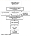 |
Fig. 1 Showing scope and stages of research presented in this paper. Source Author. |
2 Research approach and methods
2.1 Research overview
This case study research aims to contribute to knowledge gaps notably in providing case specific feedback on deep energy retrofit utilising innovative modular circular solutions to accelerate decarbonisation of the stock, focusing on thermal / energy performance and occupant feedback.
The overarching questions examined in this research on deep energy retrofit in social housing is; how can modular circular systems be applied in a thermal fabric upgrade, meeting deep energy retrofit requirements, and what are the thermal / energy performance impacts and tangible benefits to users.
Sub questions arising from same include: How can modular systems be developed for retrofit over cladding, integrating circularity principles and what are the key issues, challenges and benefit? How do such systems perform in relation thermal performance of the fabric and what is the impact on thermal and overall energy efficiency? How do such deep energy retrofit projects, integrating modular systems, perform for a user perspective?
To answer this the research combines both qualitative and quantitative methods in a mixed method approach based on a grounded bottom-up holistic case study [1,2] utilising various research methods and data sources, both hard and soft data, as well as practitioners and researcher knowledge and experience to explicate knowledge and insights acquired in the design and execution of a deep energy modular retrofit, providing a rich descriptive picture of the complexity and potential of modular retrofit in housing [3,4].
The case study and key issues examined are set in a contextual literature review on decarbonisation, modularity and circularity, followed by Part A setting out the case study design, development, monitoring / testing, prototyping and final manufacture and construction, with Part B reporting on pre and post works monitoring, assessments and occupant survey results, leading to commentary and discussion on findings into deep energy retrofit via modular circular solutions, contributing to current knowledge.
2.2 Research methods
i) Case study research is the principle framework for the study, examining the case retrofit performance from a variety of perspectives, and using mixed methods, both qualitative and quantitative.
ii) Literature review
A detailed literature review on modular systems in retrofit and circularity was undertaken to set the work in context and identify knowledge issues, including review of other retrofit performance assessments.
iii) Documentary / Reporting
The case study documented the design development of the retrofit works and modular wall system, including prototype mock-up, circularity assessment, pre works monitoring, testing and tenant surveys, manufacture and construction works, followed by post works monitoring, testing and tenant surveys for analysis.
iv) Computerised Assessments
Steady state U Values were undertaken based on ISO 6946 Building components and building elements — Thermal resistance and thermal transmittance — Calculation methods [5] Steady state Energy Assessment / Rating of dwellings, pre and post works based on the Irish national building energy rating calculation method − Domestic Energy Assessment Procedure (DEAP) under the Energy Performance Building Directive Framework [6].
v) Physical Testing and Monitoring
Collation, reporting and analysis of a range of physical in situ testing, monitoring and assessment, including, air pressure testing in accordance with I.S. EN ISO 9972, [7] thermal imaging in accordance with EN ISO 6781-1:2023 Performance of buildings − Detection of heat, air and moisture irregularities in buildings by infrared methods − Part 1: General procedures [8], thermal transfer of building envelope based on BRE Guide to In-situ U-value measurement of walls in existing dwellings and energy monitoring and ISO 9869 Thermal Insulation Building Element, [9,10].
vi) Tenant survey and interview
Design and execution of pre and post occupant evaluations via interviews / surveys based Drive 0 project survey and expanded version.
vii) Data analysis
Data was collated from a diverse range of design / research / construction activities including; design workshops and meetings, monitoring of manufacture, assembly and installation, and disassembly study, façade thermal performance tests and assessments, desk-based assessments including circularity assessments, DfD assessment, and energy rating / monitoring.
3 Literature review
3.1 Background and context
The building and construction sector has significant impacts on the environment including operational energy use impacts [11,12]. Globally, buildings account for around 34% of final energy use and contribute about 28% of energy-related CO2 emissions from operations, rising to nearly 40% when embodied emissions from construction materials are included [11,12]. The sector also generates significant volumes of construction and demolition waste, [13,14]. In the European Union, this waste stream represents approximately 40% of total waste generated [13,14].
The European Union is responding with significant policy and legislative initiatives toward improving the sustainability [15] and energy efficiency [16] of its building stock, including transitioning the economy and the building sector towards more circular practices [17] driven by the construction sector's high resource intensity and waste production [18,19]. Notable among Europe's policy and legal initiatives are the Renovation Wave [20] and the EU Green Deal [21], which aim to decarbonize the existing building stock, improve energy efficiency, promote renewable energy, and reduce and recover construction waste. Additionally, the Circular Economy Action Plan encourages circularity principles for the construction sector [22]. In addition, the latest revision of the Energy Performance of Building Directive [23] is increasing its emphasis on energy retrofit and expanding its assessment scope from operational energy / carbon to whole life cycle carbon.
In Ireland decarbonisation and circularity are also being promoted through the Irish Climate Action Plan [24], and the introduction of a Circular Economy Act [25], with the Irish Green Building Council developing frameworks and roadmaps to support decarbonisation and circularity of the building sector in particular [26,27].
Achieving deep energy retrofit has particular challenges, and the literature raises several issues including performance gaps in calculated to measured overall energy use and fabric thermal transfer, with differentiation in same related to age band, workmanship, and calculation methods. Coyne and Denny present a comprehensive investigation into the energy performance assessment of 8720 retrofitted dwellings in Ireland reporting that estimated energy savings are not being achieved, with widespread range in differences between theoretical steady state calculated and monitored ranging + 312 % to − 63%, averaging 18% across the sample stock, with the under estimation in more energy efficiency dwellings and over estimation in lower efficiency with significant variations in packages of measures some including negative energy impacts [28].
Specific case studies provide more detailed insights in specific case variables and issues. Gupta and Gregg report on a performance assessment of deep energy retrofit comparing an older Victorian age dwelling upgrades to a more modern dwelling retrofit in the UK, with results indicating a CO2 performance gaps of +28 % greater than predicted for the Victorian dwelling and + 34% for the modern dwelling. Actual thermal transmittance for the Victorian upgrade was similar to calculated target but for the modern were nearly double the estimated. Both occupants reported process unsatisfactory and inconvenient but satisfaction with outcomes [29].
A comparative study on the deep energy retrofit of two 1950's semi-detached houses in the UK, which were also overclad with modular retrofit systems as part of a UK funded wider scale retrofit project, ‘Retrofit for the Future’ programme, noted that only three out of 37 properties achieved carbon emissions reduction of over 80%, and 23 achieved a reduction of between 50% and 80% [30]. This modular retrofit included instrumental performance monitoring before and after the retrofit establishing a 42% improvement of building energy performance as result of the retrofit, and reported considerable thermal, health and wellbeing benefits from user survey and questionnaires. The project also highlighted a significant discrepancy in excess of 60% between theoretical and measured U values for the post-retrofit case, calling for a review of use of theoretical models [31].
A similar case study but within a highly controlled and monitored environmental context was conducted by the Salford Energy House, an environmental testing champer for testing the energy performance of buildings under controlled simulated weather conditions, comprised detailed monitoring of a shallow piecemeal retrofit compared to a whole house deep energy retrofit. Fabric thermal performance testing took place at each stage of the retrofit process to assess the benefit and unintended consequences of applying retrofit measures individually and in combination. Overall, the energy findings show that both approaches achieved a reduced heat transfer coefficient (HTC) of circa 50%, primarily from the External Wall Insulation wall upgrades (EWI) contributing 78% of the reduction. Interestingly the primary benefit of the whole house approach was the reduction in risk of surface condensation and mould growth at junctions, with 75% of junctions at risk at baseline reducing to 33% for the piecemeal approaches with the eaves and ground particular risk areas, resolved in the whole house upgrade. The project also highlighted a performance gap with the whole house approach retrofit measures underperformed by 5% and external wall insulation (EWI) by 17% [32].
3.2 Modularity in construction / retrofit
Modular construction is a method of construction where building elements are constructed off site in more controlled factory environments, typically in prefabricated parts or modules that are assembled on site with faster construction times and claims of higher quality [33]. Modular construction key advantages are claimed to be standardisation and simplicity, enabling mass production, time and cost saving, flexibility in maintenance, adaption and removal, and customisation via interchangeable parts and modular components leading to adaptability in design [34–37].
There is growing interest, innovation, research and development taking place in Europe in the application of modular construction systems to building energy retrofit, with several projects demonstrating possible pathways and solutions.
Annex 50 working group of the International Energy Agency (IEA) demonstrated and developed guidance for the application of standardised highly insulated prefabricated facades to apartments via six demonstration projects across Europe claiming advantages of enhanced energy efficiency and comfort, optimised constructions quality and cost efficiency, increased space and functionality, and faster retrofit times with lower impacts to occupants. [38].
Simona D'Oca et al, reviewed some 31 EU funded projects dealing with deep energy retrofit with a significant number including some level of prefabrication either in energy systems or facades [39], with some examples being; the iNSPIRe project (Systemic Energy Renovation of Buildings, 2012-16), which developed off-site pre-fabricated timber based modular facade systems for energy efficient renovation of buildings, including energy system elements such as micro heat pumps and ductwork [40], and the MORE-CONNECT project (2014-16), which demonstrated cost effective retrofit solutions to NZEB (Nearly Zero Energy Building) targets based on pre-fabricated multifunctional modular elements for both façade and roof with integrated installation of building services such as PV, ventilation and shading devises, resulting in high performance envelopes delivered at speed with on-site installation reduced to five days compared to conventional two months [41].
A diversity of approaches, methods, and construction solutions for modular energy retrofitting has emerged including; opaque, modular pre-fabricated vertical facade panels of wood and lightweight materials [42], flexible wood-based facade systems which are adaptable to timber, concrete and brick structures, as well as different tolerances and geometries [43], a preassembled insulated panel for the retrofit of facades, based on two textile reinforced concrete thin precast layers rigidly connected to an EPS core and a preassembled timber panel for existing pitched roofs [44,45], as well as systems integrating renewable energy integration [37], all applied in a diversity of climatic, national and building typology contexts across Europe [39].
Several issues have been identified in the literature with Hu Du et all in their review of Modular Facade Retrofit with Renewable energy technologies (MFRRn), identifying several categories and key issues including; technical − modular design / fixing methods, embedding renewables and coping with site variation / tolerance, and financial (financial performance and market penetration, business models and supply chains, and warranty / servicing) [37]. Torres et al. highlight the two key technical issue being integration in diversity of real-life buildings and adaptation of systems to irregularities in buildings [45]. Pope in a review of European projects noted key issues for mainstreaming at scale being, multi stakeholder supply chain development, regional variation in regulations as a barrier, developing common protocols, data transfer and tools for building data capture and sharing, coping with diversity in building typologies and architypes, and developing innovative financing, notably for the tenant owner issue, noting that until the market develops scale Governmental input may be needed to help develop the sector, and that until volume is achieved, which should drive down costs and increase investment and recruitment, the sector may remain marginal [46]. In their detailed review of four Horizon 2020 funded projects, (4RinEU, P2ENDURE, Pro-GET-OnE, MORE-CONNECT), Simona D'Oca et al, highlight that key challenges are not technical but related to awareness, knowledge and excessive investment costs [39].
An interesting modular retrofit mainstreaming initiative is the Energy Sprong Global Alliance, who are establishing market activation teams across several EU countries to accelerate the learning from pilot modular retrofit over-cladding into scalable regional and national supply chains, with an estimated 10,000 homes already decarbonised, via multi stakeholder collaboration and activation of building owners, residents, innovative companies, governments and financiers, and unlocking robust business models [47]. Circular Reno is one such project initiated by Energy Sprong under EU Interreg NW funding supporting modular retrofitting upscaling operating across six European partner nations, The project is delivering a second round of pilot modular retrofit projects in Ireland, (after Drive 0) with a focus on biobased materials [48], on which the author is actively engaged and researching.
3.3 Circularity
Circularity, in contrast to the linear 'take, make, waste' production model, seeks to keep resources circulating within an economy or supply chain, thereby minimizing resource input and waste output at the end of a product's life [49]. This concept is built upon earlier ideas [50] such as architect Walter Stahel's self-replenishing spiral loops and product life factor [51], Lyle's regenerative design [52], and the cradle-to-cradle approach by Braungart & McDonough [53]. Circularity is emerging as a significant area of research in the built environment, with a growing body of literature [54,55], yet currently, there is no standardised definition of circularity, with various definitions, criteria, and metrics present in existing literature [56–58]. In the building context, design for disassembly (DfD) is viewed as a fundamental element and “the key to enabling circular processes” [59], as it facilitates the re-utilisation of elements, components, products, and materials back into the supply-use chain [60–62].
Both circularity and the implementation and practice of DfD have been recognised as areas lacking research, particularly in terms of comprehensive assessment methods that encompass the entire building life cycle [63–68]. Specific methodological gaps highlighted in the literature include the need for integrated circularity assessment tools for construction [69], decision-making support tools for the early stages of design [70], and case-specific verification [71–73]. There is also a demand for the establishment of comprehensive indicators [65,69,71,74,75] and the quantification of performance, benefits, and value [59,72,73]. Technological knowledge gaps also persist, including advancements in DfD that facilitate deconstruction for reuse, increased standardisation with fewer components, and the disassembly of existing structures [76]. Additionally, there is a need to explore the connection between modularity and circularity, as well as off-site manufacturing and construction with practical examples [77,78]. Barriers to the development of circular solutions and typologies have also been identified [79], along with the necessity to del
PART A: DESIGN, PROTOTYPE, PRE WORKS ASSESSMENTS, REALISATION
4 The retrofit case study
4.1 Case dwelling − energy benchmark
Drive 0, an EU ‘Horizon 2020’ funded project, sought to demonstrate accelerated decarbonisation of the building stock via deep energy retrofits utilising modularised circular systems across several European demonstration cases, [80]. The Irish demonstrator proposed a deep energy retrofit, targeting a 65% energy efficiency improvement of two partially retrofitted 1970's semi de-thatched two-story houses of traditional masonry and timber construction, which is a representative typology of housing in Ireland. The main project innovation was the development of novel ‘2D’ modularised panels for upgrading of the walls and provision of a simple extension via a ‘3D pod’ both incorporating circular design strategies. See Figure 2 showing general arrangement drawings of the dwellings and front elevation photo.
A preliminary energy study was undertaken to establish energy rating benchmarks and facilitate an initial retrofit proposal for design review and tenant discussions. The energy study was based on the Irish asset-based national Building Energy Rating methodology (DEAP) under the Energy Performance of Buildings Directives, which indicated that as originally built, (based on uninsulated constructions and solid fuel ranges and open fires), the houses would have performed at the lowest D band, whereas due to partial historical retrofit measures they were now rating in B and E bands respectively. While both properties previously had attic and pumped in cavity wall insulation installed, there were significant differences, with House A, having a modern high efficiency heat pump and modern windows installed, rating at B2 rating (117.32 kWh/m2/yr), and the other House B, still using the original solid fuel range and having a poorly insulated attic room conversion in the roof space, thus increasing its floor and heat loss surface area with a poorer average U value, rated at E2 (350.36 kWh/m2/yr). See Figure 3 showing pre and post energy rating performance (based on primary energy and excluding cooking and appliances).
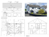 |
Fig. 2 Showing general arrangement drawings and plans of the semi-detached houses and photo of front elevation. Source Westmeath County Council / TUDublin − Author. |
 |
Fig. 3 Showing pre and post energy assessments using the Irish national energy assessment method for dwellings (DEAP − Dwelling Energy Assessment Procedure), showing significant differences in baseline energy rating, mainly due to presence of heat pump and target energy improvement and differences in estimated targets. Source TUDublin Author. |
4.2 Tenant survey and retrofit proposal
Both tenants engaged in an informal survey and semi structured interview, which provided important information regarding their use of the dwellings and energy systems along with comfort and health issues, which fed into a design strategy and supported energy analysis and monitoring data collation. Critical findings from this engagement related to air quality and health issues, with, in one case, the use of traditional solid fuels / stove resulting in high ash and dust content, and in the other case a family with an asthmatic child. This resulted in a strategy to not only provide energy efficiency solutions but also to radically improve the air quality of the homes, via fuel and stove replacement and integration of alternative mechanical ventilation systems.
A retrofit proposal was developed to achieve the 65% energy reduction target, based on common fabric upgrade to both houses with tailored systems and renewables upgrade. The proposed fabric upgrade involved conventional external wall insulation (EWI) system to the rear and sides with replacement triple glazed windows and doors all round and the demonstration of 2D modular circular wall panels to the front to achieve an upgraded target U value of circa 0.18 − 0.2 W/m2k, complemented by the addition of an extension porch lobby ‘3D Pod’ of similar modular construction to the front. (The limitation of this measure to frontage only was due to budget reasons). For systems upgrade, House A, which had an existing heat pump, was proposed to have mechanical ventilation with heat recovery (MVHR) installed along with a photovoltaic (PV) array. The other House B was to have its original solid fuel range replaced with a biomass pellet stove boiler, installation of demand control mechanical ventilation (DCMV) and a PV system. See Figure 4 showing simplistic concept schematic of range of upgrades presented and discussed with tenants.
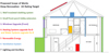 |
Fig. 4 Concept schematic of package of upgrades for tenant briefing, identifying proposed fabric, heating, ventilation and renewable energy upgrades. Source TUDublin − Author. |
4.3 Modular wall system
The Irish demonstrator included the first known pilot of modular systems in retrofit application in Ireland, based on adapting an existing light gauge steel (LGS) structural wall system to function as a demountable, pre-finished ‘closed’ wall panel incorporating circularity principles, including advanced DfD at all levels in its construction hierarchy and utilising biobased materials where possible in the construction. Early concept proposals tackled issues such as installation of panels under existing eaves, disassembly potential and details concerning bracketry and connection of panel to host wall and facilitating tolerance to rear of wall panel and avoiding thermal looping. See Figure 5.
Parallel with this early design stage analysis a circularity assessment method was piloted across all Drive 0 demonstrators, which highlighted the key aspects of circularity being focused on in the Drive 0 project namely, embodied energy and carbon, design for disassembly (DfD), biobased materials and urban mined materials. This influenced design direction for the Irish modular solution with a focus on DfD and biobased materials, as urban mining, (process of reclaiming raw materials from existing construction waste products) was not considered an option in Ireland given barriers concerning certification of second-hand materials [81]. Embodied energy (EE) and carbon (EC) assessments of the modular system compared to a conventional external wall insulation system, showed that the additional layers and framing of the modular system resulted in higher EE and EC over one lifetime, which focused attention on further simplification and utilisation of biobased materials.
 |
Fig. 5 LHS conventional application of LGS system and RHS preliminary proposed panel construction targeting a combined modular panel existing wall U Value of 0.18 − 0.2 Wm2k. Source Vision Built, Coady Architects. |
5 Detail design, prototyping and pre works assessments
5.1 Detail design and prototype planning
Early design concepts of the modular system were developed over several workshops into detailed architectural − technical designs with working drawings covering all the major panel types and junctions and integrating emerging concepts for optimising DfD in all hierarchical levels and biobased materials. In parallel preparations were made for a prototype mock-up, which was designed to represent all 2D and 3D panel types / junctions at scale and to test the manufacture, installation and assembly, finishes and connection details and notably included a comprehensive physical audit of DfD performance of the panels involving full disassembly and reassembly at all levels of hierarchy [82]. See Figure 6 showing schematic of mock-up design, which covered all envisaged panel and junction types.
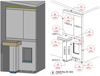 |
Fig. 6 Initial 3D images of mock-up with five panels representing all the major envisaged panel types and junctions. Source Vision Built. |
5.2 Prototype execution
The execution of the prototype mock-up itself went through three main stages as follows;
Stage 1.
The original mock-up panels, involving three 2D wall panels and extension roof and wall panels, were manufactured, assembled and installed on an external test wall at the factory for visual inspection and a period of external weather exposure. See Figure 7 showing Stage 1 of the original prototype mock-up installation process.
This stage provided important insights and was critiqued in terms of;
i) the bracketry needing too much packing and not facilitating sufficient tolerance movement, which became more critical given the point cloud survey plumbness study.
ii) the rear air gap backing material / fixings and the neoprene perimeter being too rigid for compression,
iii) the render finish being of poor quality with chips and marks and panel joints not well aligned, and visibly noticeable, (along with delays in factory completion due to wet trades)
iv) concerns about water ingress at horizontal joint band and
v) poor quality and detailing at roof to wall junction.
A comprehensive physical audit of DfD performance was undertaken during manufacture and assembly and of the de-installation of all panels, disassembly of window to wall components and full disassembly of one of the upper panels, with detailed assessment of process and impacts. The audit showed that disassembly had minimal impact on core materials and products, save for some impact on joint materials − horizontal (taping) and vertical (butyl seals) joints [83].
Stage 2.
The upper panels were then re-assembled using all original materials, but with new dry cement board as a proposed alternative dry finish and re-installed using new revised bracket design to facilitate greater tolerance movement, with these design decisions being incorporated into the final design. The DfD audit at this stage demonstrated that all core materials were salvageable and could be reused in the re assembly, excluding fixings, some 50% of which were damaged (and were also noted as excessive in number and type). See Figure 8 showing Stage 2 mock-up installation with revised bracket facilitating more tolerance movements in three planes and the change of finishes from wet render to dry cement board demonstrated in the upper panels. Open joints were later closed with metal back strips.
Stage 3.
The final mock-up involved installation of a partially completed full size panel under a mock-up eaves projection utilising a counter weighted hoist to facilitate vertical placement of the panel below the eaves, which was utilised in the actual retrofit.
Overall, the design and execution of the prototype mock-up was an essential stage in the design development process and raised / resolved several key specification, detailing and installation issues, as well as showing that the design strategy for advanced DfD was working in practice and indicated utility and broad validity of the design stage STaMPD DfD assessment method [83].
 |
Fig. 7 Original mock-up showing − above LHS rear of panel with compressible insulation and perimeter gaskets, RHS original brackets and below − LHS first panel installation in progress, RHS wall panels installed. Photos source Vision Built, TUDublin Author. |
 |
Fig. 8 Mock-up Stage 2 with LHS revised brackets allowing for minor tolerance in three planes, Centre − revised upper panels with new cement board lining and RHS − revised backing insulation. Photos Source Vision Built. TUDublin Author |
5.3 Monitoring design and pre works installations
A comprehensive monitoring system was designed for the specific dwellings, which incorporated detailed energy monitoring, including full disaggregation of heating and power, as well as air quality (relative humidity and carbon) and people movement. The installation of monitoring equipment required specialist researcher briefing and directions to plumbing and electrical installers, but problems were encountered in House B as it was discovered the standard of electrical wiring was insufficient and needed upgrading before electrical monitoring could proceed or indeed retrofit of energy services and technologies. Some aspects of energy could not be remotely monitored such as solid fuel consumption and required data collation by tenants with briefing on same for estimation. These issues resulted in a mixture of calculated, monitored and predicted energy use being required at end of project for performance assessment.
5.4 Pre works façade assessment / testing
Additional survey, assessment and testing was undertaken to support more detailed building geometry data capture, and more refined assessment of pre works fabric performance involving;
i) a point cloud survey to support production of modular panels to case specific dimensions, which highlighted the significant lack of plumbness in the existing wall both vertically and horizontally, influencing panel bracket design and rear panel air gap / tolerance zone insulation to avoid thermal looping, (air movement within gaps of insulation, of cavity, forming a continuous cycle of rising warm air and descending cold air that significantly reduces the insulation's effectiveness).
ii) existing cavity wall scope / camera study to ascertain extent of existing blow in insulative bead coverage, which proved to be poor quality and inconsistent.
iii) insitu cavity wall thermal transfer site measurements, which indicated existing equivalent U Value thermal transfer of 0.99 − 0.1 W/m2k, which contrasted to calculated U Value of 0.37 W/m2k (and DEAP method default by age band of 0.6 W/m2k), with differences principally attributed to poor and inconsistent coverage of blow in insulation beads evident from scope camera study and later visual inspection, and to some extent the U value simplified steady state calculation method.
iv) thermal imaging, which showed inconsistent thermal profile and local heat leakages at window heads, cills, jambs and service penetrations, and
v) air pressure testing with pre works permeability q50 (m3/hr/m2) values of 7.5 (House A) and 12.5 (House B), with the main leakage identified in the façade windows and service penetrations and significant leaking in the attic room and first floor ceilings of House B.
See Figure 9 showing some of the facade assessments undertaken.
 |
Fig. 9 LHS Thermal imaging of front part rear elevation House A showing heat leakage at door, heads and eaves, Centre − on site measurement of thermal transfer, RHS − air pressure testing blow door fan. Photos Source TUDublin Team, Author. |
5.5 Circularity / DfD Assessment and strategy
By this stage in the design development of the modular system several Drive 0 circularity − DfD assessments had been undertaken, which not only influenced the Irish circularly design strategy, but also facilitated critique of methods with argument for necessity of taking a hierarchical perspective to retain highest ‘value’ at all construction levels, [81]. Based on this concept the Irish design specifically focused on achieving advanced DfD at all levels in the construction hierarchy, (wall panel level, component level and product / material levels), with this concept integrated into emerging designs and the design of the prototype mock-up itself, which included a physical audit of actual DfD performance, to compare with a novel design stage DfD assessment framework and method entitled STaMPD, an acronym for Systems, Technical, Materials, Process and Data [82,83]. See Figure 10 showing circularity DfD concept for Irish modular system at three levels of hierarchy.
 |
Fig. 10 Showing concept schematics of panel DfD design in three hierarchical levels. Source TUDublin team, Author. |
6 Final design, manufacture and construction
6.1 Final design and preparations
Findings from the prototype mock-up were integrated into revised detail design drawings and specification for the modular panels, incorporating revised bracketry and cement board finishes with some changes to extension roof design, flashings and finishes, which fed into revised production drawings for manufacture. The changes in material finish required further development and revision to architectural design and re-engagement with planning authorities by the architects. Parallel with same, final design drawings of the retrofit with outline specification of fabric, services and renewables upgrades were developed and presented to the tenants. During this final design phase site inspections were also carried out by all the specialist services and renewable providers to co-ordinate and finalise layouts, scope, budgets and prepare for installation. Making good to the substandard electrical wiring to House B was also carried out to facilitate monitoring installation and retrofit works. Contract documents and programmes were developed, which were influenced by long lead items such as windows and doors. See Figure 11 showing final general arrangement drawings and concept 3D image of elevations.
 |
Fig. 11 LHS − General arrangement front elevations and 3D rendered images of front elevation produced by architects during final discussions with planners. Source Coady Architects. |
6.2 Manufacture and assembly
Following final design approval, drawings and specification and ordering of long lead items such as windows and some key materials was undertaken, while the manufacturers commenced on detail production drawings leading to factory-based manufacturing and assembly. See Figure 12 showing BIM model of modular overclad and extension pod systems to front elevation.
Manufacture was undertaken in two main stages; i) Panel Assembly-Horizontal − involving; assembly and fixing LGS frame, cutting and fixing wood fibre board, applying outer membrane and fixing battens, ii) Panel Assembly − Vertical − involving; installing windows, installation of insulation between studs, assembly of panel-to-panel connection and edge treatments, and finally dry cladding cutting and fitting.
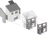 |
Fig. 12 Showing final concept of modular overclad retrofit with modular 2D and 3D systems to front elevation. Source Coady Architects / Vision Built. |
6.3 Construction works and installation
The construction process went through several stages as follows; enabling works to prepare for EWI and front modular system, installation of rear windows and EWI, the installation of the modular system via crane, which took just one day, but adaptation and finishes of same and on-site construction of the front 3D extension pod from 2D panels took longer, especially the roof elements, all of which proceeded ahead of the side and rear EWI system, fitting of window linings, making good to eaves, installation of porch lobby and installation of services and renewables.
The services and renewables included installation of i) PV systems to roof and attic with electrical output diverted to hot water heating, ii) ventilation systems − mechanical ventilation with heat recovery (MVHR) House A and demand control mechanical ventilation (DCMV) House B along with well-planned ductwork, iii) removal of original stove range from kitchen in House B for replacement with biomass chip stove boiler, which was connected to heating and domestic hot water systems, iv) and remedial airtightness works to both houses based on leakage points identified in air pressure test.
The construction of the front porch air lobby from 2D panels also commenced with adjustment of some of the ground screws, installing floor platform and then assembling wall and roof panels, with windows and doors arriving later, all of which slowed down the works. Despite some delays and issues surrounding managing a small retrofit project, including coordinating and securing different trades and specialists, and impacts on tenant lifestyles due to works on site and internally, the project was completed with immediate thermal comfort, air quality, acoustic and energy bills benefits reported.
See Figure 13 showing installation of wall overclad panels, Figure 14 showing works to eaves and porch lobby construction and Figure 15 showing near complete and completed works.
Part B: Pre & post works performance analysis
 |
Fig. 13 First upper floor full width panel being installed under projecting eaves. Source TUDublin Author |
 |
Fig. 14 LHS front 2D installation near complete with works to eaves upgrade taking place, RHS − extension porch lobby being installed / assembled. Source TUDublin Author |
 |
Fig. 15 LHS near complete front with works to porch roof ongoing PV installed and scaffold to sides and rear still in place for EWI works, RHS showing complete front elevation. Source TUDublin Author. |
7 Fabric thermal assessments
A range of assessments were undertaken to determine thermal and air leakage performance of the external envelope involving thermal imaging, air pressure testing and thermal transfer monitoring, as follows.
7.1 Thermal imaging
Thermal imaging was carried out for both houses pre and post retrofitting works, outdoors and indoors, based on guidance from EN ISO 6781-1:2023 [8] with camera (FLIR-E63900 model E6 1.2L, T198547, lens 45°) set up to match condition and facilitate pre and post works interpretative comparisons, as follows.
Pre Works Assessment
Pre-retrofit test has been carried out between 31st January and 14th of February of 2022, outdoor pictures were taken around 19pm and indoor pictures between 18 and 19pm in house A and 19 and 19 in house B.
The thermographic camera was set up as follows:
Outdoors:
T = Temperature range; e.g T0-16 = from 0deg C to 16degC
E = Emissivity; e.g. E0.95 = emissivity of 0.95 (matt surface/ concrete)
R = Reflected temperature; e.g. R20 = Reflected temperature of 20degC
D = Distance from camera to object; e.g. D15 = Distance of 15 meters
Indoors:
All Indoor Pictures using T15-25_E0.95_R20_D2
Apart bathroom using T12-27.8_E0.6_R20_D2 for one house and Apart bathroom using T15-25_E0.6_R20_D2 for the other.
Post Works Assessment
Post-retrofit test has been carried out on 10th of November of 2023, starting at 18pm and finishing at 19.30pm with and exterior temperature of 6 degrees and interior of 22-23 degrees. Heating was switched on in both homes.
The thermographic camera has been set up as follows:
Outdoors:
E = Emissivity; e.g. E0.95 = emissivity of 0.95 (matt surface/ concrete)
R = Reflected temperature; e.g. R5 = Reflected temperature of 5degC
D = Distance from camera to object; e.g. D15 = Distance of 15 meters
Indoors:
All Indoor Pictures using E0.95_R20_D2
Apart bathroom using E0.6_R20_D2
Photographic results and commentary are presented as follows; Figure 16 showing pre and post works external image examples and Figure 17 same for internal images examples.
Note − Thermal imaging pre and post works were undertaken on different dates, pre works in winter and post works in spring, in different temperature and cloud contexts, but with heating on in both properties. Camera settings were set to match some features such as range, others were automated to temperature context. Comparisons made therefore are not of temperature context or range but on temperature variations and surface spot temperatures, i.e. uniformity, consistency and leakage.
Regarding the outdoor area it was observed that on the front that the regions between the windows do not represent heat loss but rather indicate heat reflection resulting from the darker surface colour, in part due to the time of the survey photograph, and likely absorption of solar radiation during the day. Following the completion of the retrofitting works, the primary location for heat loss on the front elevation was identified at the porch entrance, which is actually a semi external unheated space. At rear elevation, an improvement was noted in the consistency of the temperature throughout the entire wall, where external wall insulation has been applied. The EWI has led to a notable enhancement in addressing heat loss concerns around eaves at gable walls with a noticeable uniformity in temperature across the entire wall. Interior thermal imaging assessments show an increment in internal temperature at the main door entrance due to the construction of a 3D outside porch. South facing bedroom showed an increment of temperature around 4 degrees, meanwhile north facing bedroom an increment of 3 degrees.
The thermal imaging test results present a notable improvement in exterior conditions, showing a more consistent and uniform surface temperature and is indicative of a successful reduction in thermal bridging. Concurrently, the internal wall surface images show an increase in surface temperature, likely due to improved thermal insulation in the fabric. These findings indicate that the measures undertaken to enhance thermal performance of the fabric were effective in measure and reduced thermal leakage.
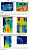 |
Fig. 16 Outdoors thermal images before and after renovation. Source TUDublin Team / Author. |
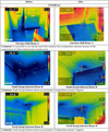 |
Fig. 17 Indoors thermal images before and after renovation. Source TUDublin team / author. |
7.2 Airtightness
A series of air pressures tests using blower door equipment and leakage audits with use of smoke sticks and visual inspection were conducted during the project, in accordance with I.S. EN ISO 9972:2015 [84] one pre works, one during works to assess remedial actions and one post works.
House A
The preliminary pre works blower door test at House A yielded an average result of 7.5m3/(hm2) at 50 Pa with windows and doors, vents and some services penetrations identified as main leakage paths. An intermediate test was conducted, incorporating both the initial renovations and subsequent remedial interventions, with the test recording an airtightness level of 8.84m3/(hm2) at 50 Pa. The final assessment, conducted post-completion of all works, reported an airtightness result for of 8.23m3/(hm2) at 50 Pa, which showed that remedial works were not effective or completed.
House B
The initial blower door assessment at House B revealed an average reading of 12.39m3/(hm2) at 50 Pa with the attic room, first floor ceiling and some service penetrations the source of most leakage. An intermediate test was conducted, encompassing subsequent remedial measures registering an airtightness level of 10.79m3/(hm2) at 50 Pa. The final test achieved an improved reading of 9.94m3/(hm2) at 50 Pa, showing only minor improvement from remedial works. See Table 1 below for a summary of test results.
The most common air leakage points for the existing dwellings were noted in the wall mainly via wall vent connections and windows / doors opening sections. Services penetrations in the envelope, soil pipes, waste pipes, cables, etc. were also causing some leakage. There was significant additional leakage at ceiling level and attic room of House B, including excessive services openings and damaged plasterboard from the attic in the cylinder storage area.
A comprehensive air leakage audit and assessment was undertaken with leakage points identified and reported for remedial action and upgrade, however only some of these seem to have been attended and the air tightness improvements envisaged were not achieved. Air pressure testing and auditing may have been better if carried out at several key stages during the works by the contractor with trades persons present.
Blower door test results. TUDublin Author.
7.3 Thermal transmittance (Equivalent U Value)
Monitoring of the thermal transfer across the front elevation wall of House A was conducted both pre and post works based on BRE Guide to In-situ U-value measurement of walls in existing dwellings [9] and ISO 9869-1 Thermal Insulation Building Elements 2014 [10] to determine and compare heat transfer across the original and retrofitted walls and to calculated U value targets. Greentech thermal flux sensors and data loggers were used to collate air and surface temperatures inside and outside. See Figure 18.
To protect the outdoor air temper sensor from rain and solar radiations a garden pot was adapted to form a rain and solar shield, with an opening for allow air circulation. the heat flux and air temperature sensors were at ∼3-4m from the closest heat sources that are a radiator and a chimney. Therefore, there is no direct convective heat affecting the heat flux. In front of the radiator is a sofa and a door preventing direct radiative heat from the radiator to reach the wall studied. The same direct radiative heat from the chimney reaches the wall and the sensor. To avoid heat flux variations and maintain a temperature difference with the outdoor above 5°C, the occupants were instructed not to open the window during the measurement period and to keep the living room door closed as often as they can without inhibiting their comfortable use of the house. No problem on potential variations of the setup were reported by the occupants during the period of measurement.
 |
Fig. 18 (a) position of sensors on the south facing wall viewed from the indoor; (b) close-up view of the indoor heat flux and air temperature sensors; (c) position of sensors on the south facing wall viewed from the outdoor; (d) garden pot serving as weather protection for the outdoor air temperature sensor; (e) view from below of the pot showing the opening used to increase air ventilation and the outdoor air temperature sensor. Source TUDublin Team. |
Pre Work Thermal Transmittance Results
Several periods of analysis were undertaken at 1 min intervals over 2022-01-31 to 2022-02-07 with U values calculated based on based on ISO 9869-1-2014 with results ranging from 0.98 to 1.04 W/(m2.K) with acceptable standard deviations. See Figure 19.
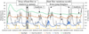 |
Fig. 19 Showing periods of analysis and times discounted due to effects of window and fire in use for pre works thermal transmittance monitoring. |
Post Works Thermal Transmittance
Based on the same set up and time intervals, over the analysis periods of 624h circa one month between 2023-02-22 and 2023-03-20 the average U Value was 0.23 W/(m2K). Results show a significant reduction in fabric heat loss of 77%, from a Pre works transmittance of 0.99 W/(m2K) to post works at 0.23 W/(m2K). See Figure 20.
This study also highlights significant differences to estimated performance from U value calculation and default U Values within the DEAP method as per the Table 2.
The U value for the original pumped cavity wall based on DEAP defaults for construction type and age bands would be 0.6 W/m2k, adjusted to 0.19 W/m2k and 0.2 W/m2k for modular system and EWI upgrades. This compares to external wall steady state calculated U Value at 0.37 W/m2k and upgraded to 0.15 W/m2k and 0.19 W/m2k for modular and EWI retrofit. Comparison to monitored actual thermal transmittance of 0.99 W/m2k equivalent U value for original wall and 0.21 W/m2k with modular upgrade, shows significant differences to U value calculations, with the difference attributed to likely poor cavity wall pump distribution and consistency, as was evident from cavity wall scope examination, and to some extent to the U Value calculation method simplicity.
 |
Fig. 20 Showing results for post works thermal transfer with modular wall over cladding at same location as pre works. |
Showing comparison of calculated wall U Value and equivalent thermal transmission results from actual Source TUDublin Author.
8 Energy monitoring results
8.1 Monitoring introduction
Following completion of works, including upgrade of wiring to House B, and installation of additional post works monitoring equipment for ventilation systems, heating / hot water system and PV systems, post works monitoring was commenced. Data was collated for heat, power and air quality and included disaggregation of electricity to cooking, lights, DHW, kitchen appliances, etc. See Figure 21.
There were some issues during the monitoring project, which resulted in need for estimations and forecasting including; use of solid fuels, House B pre works electrical monitoring being affected by substandard electrical wiring, some sensor damaged and removed during works and overall delay in the project effecting monitoring results period and data collation.
 |
Fig. 21 Showing concept monitoring plans for one of the two houses. |
8.2 Energy results
Interim energy monitoring results are presented here for each dwelling noting the following
That the dwellings used different heating systems and fuels, notably House A being ‘all electric’ with space and water coming mainly from the heat pump, but with some minor secondary space heating from solid fuels in a room stove (which were ignored in results), and House B using solid fuel for both pre and post works, requiring fuel and energy estimation from tenant data.
That the installation of electrical monitoring devices to House B could not proceed pre works given safety concerns with wiring condition of dwelling and as such pre works electrical energy was calculated from bills.
Pre works monitoring was for circa 1 yr (Jan to Dec 2023) and post works reported monitoring is four months Jan 23 to May 23.
Post Works monitoring analysis and reporting was completed to April 23 with predictive results being estimated for the entire year.
External air temperature was also monitored over pre and post works, but minor season variations, but given that the results were interim and comprising both monitored and calculated results, and projected over 8 months, weather adjusted results was not considered critical.
Results include a combination of monitored, estimated and predicted energy use.
House A
House A is effectively an ‘all electric house’ as its main space heating is coming from a previously installed heat pump supplying both space and water heating. Minor use of solid fuels in the living room stove was ignored, with heating supply being used to disaggregate the electrical energy consumed by the heat pump into space and water heating.
i) Heating Supplied
The heating supplied (as an output of the heat pump) is reported and disaggregated to space and water, showing a minor and near constant DHW rate compared to the clearly seasonal variation in space heating. The ‘pre and post’ works monitored results indicate an approx. 36 % space heating supply reduction over the monitored period, due to fabric improvements. See Figure 22.
ii) Electrical Energy Use − Including Heating (Total Energy)
The electrical energy results are effectively the total energy as House B is ‘all electric’ with fully disaggregated results presented, including electrical space and water heating, showing pre and post monitoring and predictive total energy. The ‘pre and post’ works results indicate circa 16% electrical energy reduction over the monitored period, which compares with a 21% total electrical energy reduction from the combined monitored − predicted annual period with a saving of 1,079 kWh resulting mainly from the fabric upgrade. See Figure 23.
 |
Fig. 22 kWh Water Heat Supplied by Heat Pump Pre Works (Left) and Post Works (Middle) and Water Heat Supplied by Heat Pump Pre vs Post Including predicted (Right). Source TUDublin Team, Author. |
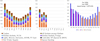 |
Fig. 23 Electrical energy consumptions (kWh) Pre works with no PV (Left picture), Post works has PV (Middle picture) with Pre vs Post including predicted (Right picture) Source TUDublin Team, Author. |
House B
i) Heat (Solid Fuel)
Heating energy consumption for pre works solid fuel range and post works stove / boiler is calculated from a combination of tenant data and hot water supply outputs noting a change in both fuel − originally turf and coal to pellets post works, and also in efficiency, an old solid fuel range (60%) to a modern stove boiler (83%). The space heating energy reported shows a significant 68 % reduction over the monitored period and a 62% reduction from the combined monitored − predicted annual period. See Figure 24.
ii) Electrical (excluding heat)
There was no pre works electrical monitoring, due to condition of electrical wiring, however pre works electrical energy was assessed from 3 yr bills data.
The ‘pre and post’ works results, which include PV generation, indicate circa. 45 % electrical energy consumption reduction over the monitored period, which compares with a 43 % energy reduction from the combined monitored − predicted annual period. This is likely due to a combination of PV generation and PV electrical energy contribution direct to DHW cylinder thereby reducing dependency and use of secondary electric immersion reported by tenants pre works. See Figure 25.
iii) Total
Pre and post works comparisons of total energy are a combination of monitored, estimated from bills and predicated, showing significant 60% energy reduction mainly from fabric improvements, stove boilers efficiency improvements and PV generation, which is supplied firstly to DHW heating, with DHW heat reduction. See Figure 26.
 |
Fig. 24 Energy consumption for space heating monitored (kWh) Pre (turf & coal in range) Left graphic. Post (pellets in 11kW biomass burner) Middle graphic and predicted post-phase space heating consumptions (kWh) Source TUDublin Team, Author. |
 |
Fig. 25 Electrical energy consumptions monitored (kWh) Pre (no PV) left graphic. Post (PV) right graphic. And predicted Post-Phase Electrical Consumptions (kWh) Source TUDublin Team, Author. |
 |
Fig. 26 Energy consumptions (including from solid fuel and excluding from PV) (kWh). Pre works left graphic; post works middle graphic and energy consumptions (including from solid fuel and excluding from PV) (kWh). Pre vs Post (including predicted) left graphic. Source TUDublin Team, Author. |
8.3 PV
A PV study for both dwellings, shows seasonal variation and differences in output, (due to slight difference in array sizes), and significant difference in self-use of generated power in House B, which utilises PV generated electricity to domestic hot water. See Figure 27.
 |
Fig. 27 PV Electricity Generated (kWh) RHS House A showing seasonal variation and lower output, given small array, and small self-use portion compared to House B LHS. Source TUDublin Team, Author. |
8.4 Energy summary
The energy monitoring study has indicated that the retrofit measures resulted in significant reduced energy consumption relative to the pre works efficiency and specification of the dwellings and the extent of works undertaken, notably with significant fabric improvements in both dwellings, heating system improvements in House B, and combined PV renewables in both dwellings. Results for House A show a reduction in total energy circa 21% resulting mainly from reduced space heating (via improved thermal performance of fabric) and PV contribution. Results for House B show a significant reduction in total energy of circa 60%, combining a 62% heating reduction in heating and approx. 42% reduction in electricity, due to improved thermal performance of the fabric, improved stove/boiler efficiency and PV contribution. The significant differences in energy savings between properties is mainly due to the different baselines and the existing high (circa 300%) efficiency of existing heat pump in House B resulting in improved fabric thermal performance having lower relative energy savings.
These monitored results compare with steady state estimated energy reductions from the DEAP BER method of circa 72%, which is not directly comparable to monitored results as the scope of DEAP excludes cooking and appliances. This comparison of estimated (DEAP/BER) to monitored results highlights the ‘performance gap’ phenomena evident in the literature review, with significant differences in energy estimates and actual performances. (See Fig. 3 showing estimated steady state energy baseline and post energy upgrade from DEAP method, showing BER ratings for each dwelling).
Table 3 compares the energy results from both assessed and monitored-predicted results showing comparison of partial scope steady state DEAP Building Energy Rating assessed results, to monitored − predicted data highlighting differences between the simplified assessment method and more complex reality, with results also needing qualification and interpretation given that some pre works monitoring was supplemented with calculation (solid fuels), and post works annual energy is a combination or monitored (four months) and predictive, and in places needing supplemental calculations.
Monitored-predictive total energy results for House A are circa 45% lower than DEAP assessment for pre works and circa 50% higher for post works. House B monitored predictive results are circa 62% lower than DEAP assessment for pre works and 36% lower for post works. While DEAP assessment indicated energy reductions averaging 72% across the two dwelling the monitored − predictive results averaged 40% ranging from 21% for House A and 60% for House B. A significant portion of this performance gap likely arises from the scope of assessment with the DEAP method being steady state and asset-based − thereby excluding cooking and appliances, and so not representing full electrical or total energy consumption and also having several modelling simplifications notably around occupancy, comfort temperatures and weather data. The significant difference in calculated U Value to monitored equivalent, as noted in section 6.3 is also an important factor in this case and would contribute to the performance gap.
Pre and post works DEAP energy rating and monitored − predicted results comparison, showing performance gap. Source TUDublin Author.
9 Post occupancy assessment
9.1 Survey approach
The aim of the occupancy survey was to ascertain tenant knowledge and experience of the dwellings both pre and post works and general perspectives in relation to circularity and retrofit.
Pre works survey
A pre works tenants survey and informal interview was conducted using the Drive 0 survey form as pre-issued to tenants and a supplemental survey on the existing energy systems.
Post work survey
Post-occupancy evaluation was conducted on site and was separated into two primary sections in order to allow for pre and post works comparison with section 1 being the same as the pre works survey and a comprehensive additional post occupancy survey was created to get the tenants feedback on a variety of topics.
9.2 Survey results
Despite the comprehensive retrofitting efforts aimed at enhancing circularity and environmental consciousness, there has been a notable lack of value or understanding of these aspects from both families involved. Surprisingly, the primary focus for both families remains on product specifications and requirements, overshadowing considerations for circularity and environmental impact.
House A anticipated improvements in air quality, house temperature, and reduce utility bills post-retrofitting. However, the mechanical ventilation system and improved air quality were identified as the main advantage following the retrofitting works. House B retrofit successfully met their expectations by enhancing hot water systems through the installation of solar panels and pellet stove and also reported improved air quality and space utility from the extension.
Both families concurred that the delays in the work that occurred during the Christmas season were negative. Despite this setback, both families expressed a strong interest in being actively involved in the retrofitting process from its inception. They provided positive feedback on being well-informed throughout all stages, from initial ideas to final design and construction. While neither family regarded the retrofitting process as a negative experience, they did acknowledge it as a time-consuming and labor-intensive endeavor, highlighting a long and slow process with a lot of effort involved.
The survey findings reveal a notable surge in tenant satisfaction across various improvement categories. Enhanced domestic hot water, improved acoustics, superior air quality, minimised air draughts, increased natural lighting, optimised humidity levels, and more comfortable temperatures collectively contributed to heightened contentment among the tenants and lower energy bills.
See Figure 28 showing example outputs and results from survey findings.
Moreover, when assessing energy consumption reduction measures, both households unanimously agreed on the most beneficial retrofitting works being the installation of photovoltaic panels, external wall insulation, and the replacement of doors and windows.
Overall, the post occupancy evaluation showed a very favourable response from tenants to the retrofit, despite minimal engagement in circularity concepts and complaints about impacts during works and they have acknowledged perceptible enhancements in thermal comfort, reduced bills and notably air quality / health and utility space benefits.
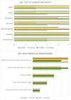 |
Fig. 28 An example of results from two of the questions undertaken in POE assessment. Source TUDublin Team. |
10 Critical commentary
This case study has met specific knowledge gaps identified in the literature and contributes to the field in explicating from case practice the potential and challenges of achieving deep energy retrofit utilising modular circular construction systems. This research examined deep energy retrofit in social housing utilising modular circular construction solutions toward optimal upgrade of the building fabric and associated energy efficiency improvements.
10.1 Main results
In relation to the main overarching question, how can modular circular systems be applied in a thermal fabric upgrade, meeting deep energy retrofit requirements, and what are the thermal/energy performance impacts and tangible benefits to users? The project demonstrates that modular circular over-cladding systems can technically and practically support delivery of deep energy retrofits in existing housing stock. The application achieved significant reductions in fabric heat loss and contributed to overall energy efficiency improvements while complying with architectural, planning, construction, and Irish building regulatory requirements. Importantly, the retrofit also delivered tangible user benefits, including reduced energy bills, perceptible improvements in thermal comfort, better air quality, and reported health benefits.
Despite these successes, the research highlights a performance gap between predicted and measured energy savings, which is an issue also reported in the literature. While DEAP steady state modelling indicated circa 70% energy reduction, monitored results averaged 40%, ranging from 21% to 60%. This discrepancy was attributed to differences in modelling scope (excludes cooking and appliances), assumptions about occupancy and comfort levels, and variances between calculated and measured wall U-values. Nevertheless, measured wall transmittance reductions of 77% were achieved, aligning with measured space heating demand reductions of 36–68%, supported by thermal imaging evidence. This suggests that modular circular systems are effective at fabric-level improvements and user comfort, but achieving predicted whole-house energy targets requires addressing modelling limitations and real-world performance variables.
10.2 Modular circular over cladding
Examining the question of how can modular systems be developed for retrofit over-cladding, integrating circularity principles, and what are the key issues, challenges, and benefits? The project confirmed the technical viability of prefabricated modular façade solutions. Panels were designed as large-format units (full storey height, dwelling width), fabricated from point-cloud survey data with tolerance bracketry and compressible rear insulation. Installation was facilitated by a Design for Disassembly (DfD) approach, with drop-in/drop-out panel strategies allowing technical independence and replacement and installation under existing eaves.
Key challenges identified include; i) the need for precise surveys to accommodate host wall variability, ii) specialised bracketry to allow adjustability and address thermal bridging, iii) jointing solutions that balance airtightness with planning and aesthetic requirements, and iv) installation constraints such as existing roof projections and surface irregularities. Alternative approaches may involve smaller or semi-closed panels, standardised dimensions with tolerance zones, and simplified build-ups with fewer fixings. While promising at small scale, the research underlines the need for large-scale demonstrations across diverse housing archetypes to test economic and technical scalability.
The project demonstrated advanced circularity principles, particularly in applying DfD strategies at multiple levels of the construction hierarchy. Panel connection and jointing strategies were designed to enable disassembly, while some use of bio-based materials was achieved. Nonetheless, limitations were evident in terms of; i) material layers, framing and fixings increased embodied carbon and energy compared to conventional EWI systems, ii) shortage of bio-based construction products in Ireland limited material circularity., iii) assessment of circularity was complicated by inconsistent definitions and diverse emerging methods. This underscores the importance of testing circularity concepts in real-world design contexts and highlights the need for simpler, standardised tools applicable throughout the design and delivery process, and more simplified modular designs with less layers and biobased materials.
10.3 Energy performance
Considering the question of how do such systems perform in relation to the thermal performance of the fabric and what is the impact on overall energy efficiency? Measured outcomes show that modular over-cladding provided substantial improvements in thermal performance. Wall thermal transfer was reduced by 77%, directly correlating to reductions in space heating demand. These improvements were confirmed by thermal imaging, which highlighted more uniform heat distribution and higher internal surface temperatures. However, the gap between predicted and actual energy savings remains a key issue, emphasising the limitations of steady-state models like DEAP, with the model not accounting for occupant behaviour, dynamic weather patterns, or real-world system efficiencies, and compounded by limitations in steady state U Value calculations compared to actual energy transfer, which are effected by other variables such as workmanship, quality etc. The study also highlights the real world challenges and complexities of undertaking energy monitoring and more critical the necessity of more nuanced modelling methods and in-situ validation when assessing deep retrofit performance. This aligns with findings from literature and notably the results strongly align with the finding from the Ljubomir and Jankovic social housing case study using modular retrofitting, which achieved a 42% energy improvement, noting a 60% gap between theoretical and measured U values [31].
10.4 Tenant feedback
Tenant insights provided data on how deep energy retrofit projects integrating modular systems perform from a user perspective? With tenant feedback underscoring important co-benefits beyond energy savings, including: i) lower energy bills ii) noticeable improvements in thermal comfort, iii) enhanced air quality, and iv) perceived health benefits linked to improved indoor environments. The finding also strongly align with Ljubomir and Jankovics, and Gupta and Gregg case studies [29].
These findings affirm that user experience is a critical dimension of retrofit success, alongside technical performance and energy metrics. The research also revealed challenges of retrofitting while tenants remain in situ, (mainly due to conventional and internal retrofit impacts) requiring careful management of disruption and tenant engagement strategies.
10.5 Sector implications
The findings of this research have several implications for the design, construction, and manufacturing sectors.
The demonstrated viability of prefabricated modular circular over-cladding systems requires transforming design practices by requiring greater integration of precision digital surveying (e.g., point cloud data) and Design for Disassembly (DfD) strategies from the outset, with likely co-design roles for manufacturers. This shifts emphasis away from traditional bespoke detailing towards standardised, modular design approaches, but it also raises challenges in accommodating housing stock geometry and construction variability, aesthetic requirements, and regulatory / planning constraints.
For construction practice, modular systems present opportunities for faster installation, reduced on-site disruption, and improved quality control, but they also require new skills, more sophisticated tolerance solutions (set out, bracketry, jointing) and careful planning around existing site conditions (e.g., roof projections, uneven façades).
For the manufacturing sector, the research underlines both opportunities and issues. On one hand, demand for large-format prefabricated panels and bio-based materials could stimulate innovation and new product markets, supporting a transition to circular construction. On the other, current shortages of bio-based products limited supply chains, and the relatively high embodied carbon of complex modular build-ups are issues that manufacturers need to address.
The study also draws attention to the need for clearer definitions and standardised metrics for circularity, since diverse and inconsistent methods currently make it difficult for manufacturers and designers to evaluate and compare solutions.
Finally, the persistent performance gap between predicted and measured energy outcomes poses a significant challenge for all sectors involved. Designers face the limitations of steady-state models like DEAP, contractors must contend with workmanship and installation quality affecting real-world results, and manufacturers are challenged to deliver systems whose tested performance consistently aligns with design expectations. Bridging this gap will require better modelling tools, more widespread use of in-situ monitoring, and stronger collaboration across the design–manufacture–construction chain.
Overall, the research demonstrates the promise of modular circular systems in achieving fabric-level performance improvements and delivering tangible user benefits, but scaling these solutions will depend on addressing technical, economic, and systemic barriers across the sector.
Follow on pilot or demonstration projects should address these issues and notably support cost analysis at various scales and deploy solutions across a wider stock typology.
11 Summary and conclusions
The research provides strong evidence that modular circular systems are a technically viable strategy for envelope over-cladding in deep energy retrofit, delivering:
Substantial reductions in fabric heat loss.
Significant related space heating energy savings.
Quality build and reduced programme for external works.
Tangible user benefits in comfort, cost, and health.
Integration of circularity principles with practical DfD strategies.
However, challenges remain in; bridging the gap between predicted and measured energy savings, (an issue not particular to modular over cladding but retrofitting in general), simplifying modular system design to reduce embodied impacts, and scaling solutions across diverse housing stock. The findings highlight the need for further large-scale demonstrations, integration of more sophisticated performance modelling, and development of clearer definitions and assessment frameworks for circularity. This research fills important knowledge gaps by providing real-world data and insights into modular circular retrofitting, presenting the first such application in Ireland, and demonstrating both the opportunities and complexities of delivering technically viable, user-centred, and circular retrofit solutions at scale.
Acknowledgments
This research was undertaken by the author based on research and design development of an Irish demonstration case, undertaken during the Drive 0 EU Horizon 2020 project Grant No 841850, (See www.Drive 0.eu for project details).
The development of the Irish demonstration deep energy retrofit was a collaboration between the research partner Technological University Dublin and the industrial partners Coady Architects, and Vision Built light gauge steel system manufacturers, with input from building owner Westmeath County Council Architectural Department.
The author would also like to acknowledge the special input and work of TUDublin team notably research assistant Paula Gallego Barril and colleague Dr Philippe Lemarchand who led the energy monitoring.
Funding
This research was funded by EU Horizon 2020 grant number 841850.
Conflicts of interest
The institution of the author received funding as above. The author has no known conflict of interest.
Data availability statement
Supportive data in relation to this research may be available on request.
Author contribution statement
Patrick Daly: Principle investigator / researcher /sole author leading in project co-ordination, research supervision, and undertaking − conceptualisation, methodology, investigation, data, analysis, visualisation, paper writing, review and editing.
Terms are defined in Text.
References
- R.K. Yin, Case study research and applications: Design and methods, vol. 53, no. 5. 2018. https://doi.org/10.1177/109634809702100108 [Google Scholar]
- R.E. Stake, The art of case study research. Thousand Oaks, SAGE, CA, 1995 [Google Scholar]
- R. Johansson, Case study methodology, 2003. [Online]. Available: https://www.researchgate.net/publication/236143987 [Google Scholar]
- L. Groat, D. Wang, Architectural research methods, 2nd edn. vol. 66, 2013 [Google Scholar]
- ISO, ISO 6946 Building components and building elements — Thermal resistance and thermal transmittance — Calculation methods, 2017 [Google Scholar]
- European Commission, Directive (EU) 2024/1275 of the European parliament and of the council of 24 April 2024 on the energy performance of buildings (recast) (Text with EEA relevance), 2024. [Online]. Available: http://data.europa.eu/eli/dir/2024/1275/oj [Google Scholar]
- ISO, I. S. EN ISO 9972 Thermal performance of buildings — Determination of air permeability of buildings — Fan Pressurization method, 2015 [Google Scholar]
- ISO, UNE EN ISO 6781 -1:2023 Performance of buildings − Detection of heat, air and moisture irregularities in buildings by infrared methods − Part 1: General procedures, 6781 [Google Scholar]
- L. Kosmina, Guide to In-situ U-value measurement of walls in existing dwellings In-situ measurement of U-value, 2016. [Online]. Available: www.bre.co.uk/uvalues [Google Scholar]
- ISO, 9879 -1: 2014. Thermal insulation building elements In-situ measurement of thermal resistance and thermal transmittance — Part 1: Heat flow meter method, 2014 [Google Scholar]
- Lucon O. et al., 2014 Buildings, in: Climate Change 2014: Mitigation of Climate Change. Contribution of Working Group, III., to the Fifth Assessment Report of the Intergovernmental Panel on Climate, Change, O., Edenhofer, R. Pichs-Madruga, Y. Sokona, E. Farahani, S. Kadner, K. Seyboth, A. Adler, I. Baum, S. Brunner, P. Eickemeier, B. Kriemann, J. Savolainen, S. Schlömer, C. von Stechow, and T. Zwickel J.C. Minx, Eds., Cambridge University Press, Cambridge, United Kingdom and New York, NY, USA. 2014, ch. 2014 Buildings pp. 671–723. [Google Scholar]
- UNEP, 2023 global status report for buildings and construction: beyond foundations − mainstreaming sustainable solutions to cut emissions from the buildings sector, United Nations Environment Programme, Mar. 2024, https://doi.org/10.59117/20.500.11822/45095 [Google Scholar]
- OECD, Global material resources outlook to 2060 economic drivers and environmental consequences, Oct. 2018 [Google Scholar]
- C. García, J. Caro, G. Gallo, F. Tonini, Techno-economic and environmental assessment of construction and demolition waste management in the European Union Status quo and prospective potential, 2024. https://doi.org/10.2760/721895 [Google Scholar]
- European Commission, The story of the von der Leyen Commission: The European Green Deal, 2024 [Google Scholar]
- European Commission, In focus: Energy efficiency in buildings, Accessed: Jun. 04, 2024. [Online]. Available: https://commission.europa.eu/news/focus-energy-efficiency-buildings-2020-02-17_en [Google Scholar]
- European Commission, Circular economy: principles for building design, Feb. 2020 [Google Scholar]
- G.L.F. Benachio, M. do C. D. Freitas, S.F. Tavares, Circular economy in the construction industry: a systematic literature review, 2020. https://doi.org/10.1016/j.jclepro.2020.121046 [Google Scholar]
- T. Joensuu, H. Edelman, A. Saari, Circular economy practices in the built environment, 2020. https://doi.org/10.1016/j.jclepro.2020.124215 [Google Scholar]
- European Commission, A renovation wave for Europe − greening our buildings, creating jobs, improving lives, 2020 [Google Scholar]
- European Commission, European green deal: commission proposes to boost renovation and decarbonisation of buildings, 2021 [Google Scholar]
- European Commission, A new circular economy action plan for a cleaner and more competitive Europe, Brussels, Mar. 2020. [Online]. Available: https://www.un.org/sustainabledevelopment/sustainable-consumption-production/ [Google Scholar]
- European Commission, Directive (EU) 2024/1275 of the European parliament and of the council of 24 April 2024 on the energy performance of buildings (recast) (Text with EEA relevance), 2024. [Online]. Available: http://data.europa.eu/eli/dir/2024/1275/oj [Google Scholar]
- C. and C. Department of the Environment, Climate action plan 2024, Ireland, Dec. 2023 [Google Scholar]
- C. and C. and the D. of A. F. and the M. Department of the Environment, Bioeconomy action plan 2023 −2025 version 2.0, Ireland, Oct. 2023 [Google Scholar]
- IGBC, Building a Zero Carbon Ireland, 2022 [Google Scholar]
- IGBC, Building a Zero Carbon Ireland: Government Policy Scorecard, 2024. Accessed: May 30, 2024. [Online]. Available: https://www.igbc.ie/wp-content/uploads/2024/02/Policy_Scorecard_Summary_FINAL.pdf [Google Scholar]
- B. Coyne, E. Denny, Retrofit effectiveness: evidence from a nationwide residential energy efficiency programme, Energy Policy, 159, (2021), https://doi.org/10.1016/j.enpol.2021.112576 [Google Scholar]
- R. Gupta, M. Gregg, Do deep low carbon domestic retrofits actually work? Energy Build. 129, (2016), https://doi.org/10.1016/j.enbuild.2016.08.010 [Google Scholar]
- Technology Strategy Board, Retrofit revealed the retrofit for the future projects − data analysis repor, 2013 [Google Scholar]
- L. Jankovic, Lessons learnt from design, off-site construction and performance analysis of deep energy retrofit of residential buildings, Energy Build. 186, (2019), https://doi.org/10.1016/j.enbuild.2019.01.011 [Google Scholar]
- D. Farmer Grant Henshaw Christopher Tsang Benjamin Roberts Richard Fitton Will Swan, Salford Energy House Fabric Performance Testing, 2024 [Google Scholar]
- Modular Building Institute, Modular Building Institute, Accessed: Aug. 30, 2024. [Online]. Available: https://www.modular.org/ [Google Scholar]
- A.K. Kamrani, S.M. Salhieh, Product design for modularity, Springer, 2002 [Google Scholar]
- T.D. Miller, Defining modules, modularity and modularization evolution of the concept in a historical perspective, in: Proceedings of the 13th IPS Research Seminar, 1998 [Google Scholar]
- T.D. Miller, Modular engineering, in: Proceedings of the 12th IPS Reseach Seminar Fuglsø, 1997 [Google Scholar]
- H. Du, P. Huang, P. Jones, Modular facade retrofit with renewable energy technologies: the definition and current status in Europe, 2019, https://doi.org/10.1016/j.enbuild.2019.109543 [Google Scholar]
- Mark Zimmermann, ECBCS Annex 50 Prefabricated Systems for Low Energy Renovation of Residential Buildings, Mar. 2011 [Google Scholar]
- S. D'Oca et al., Technical, financial, and social barriers and challenges in deep building renovation: Integration of lessons learned from the H2020 cluster projects, Buildings, 8, (2018), https://doi.org/10.3390/buildings8120174 [Google Scholar]
- INSPIRE, Final Report Summary − INSPIRE (Development of Systemic Packages for Deep Energy Renovation of Residential and Tertiary Buildings including Envelope and Systems), 2017 [Google Scholar]
- More Connect, More Connect. [Google Scholar]
- G. Callegari, A. Spinelli, L. Bianco, V. Serra, S. Fantucci, NATURWALL© − A solar timber façade system for building refurbishment: Optimization process through in field measurements, Energy Procedia, (2015). https://doi.org/10.1016/j.egypro.2015.11.641 [Google Scholar]
- K. Sandberg, T. Orskaug, A. Andersson, Prefabricated wood elements for sustainable renovation of residential building façades, Energy Procedia, (2016). https://doi.org/10.1016/j.egypro.2016.09.138 [Google Scholar]
- F. Pittau, L.E. Malighetti, G. Iannaccone, G. Masera, Prefabrication as large-scale efficient strategy for the energy retrofit of the housing stock: an Italian case study, Procedia Eng. (2017). https://doi.org/10.1016/j.proeng.2017.04.276 [Google Scholar]
- J. Torres et al., Plug and play modular façade construction system for renovation for residential buildings, Buildings 11, (2021), https://doi.org/10.3390/buildings11090419 [Google Scholar]
- H. Pope, Industrialized exterior retrofit projects: a review, in: IOP Conference Series: Earth and Environmental Science, Institute of Physics, 2024. https://doi.org/10.1088/1755-1315/1363/1/012056 [Google Scholar]
- Energie Sprong, Energie Sprong, Accessed: Sep. 21, 2025. [Online]. Available: https://www.energiesprong.org/what-is-energiesprong [Google Scholar]
- Global Energiesprong Alliance, Circular Reno-Interrreg NW Europe, Accessed: Jun. 03, 2024. [Online]. Available: https://circularreno.nweurope.eu/ [Google Scholar]
- Ellen MacArthur Foundation, Towards the circular economy: Vol. 1: Economic and business rationale for an accelerated transition, Ellen MacArthur Foundation, vol. 1, 2014 [Google Scholar]
- D.S. Shooshtarian, D.M.R. Hosseini, P. T. Kocaturk, A. P. M. Ashrad, P. T. Arnel, P.J. Doerfler, The circular economy in the Australian built environment: the state of play and a research agenda, Australia, 2021 [Google Scholar]
- W.R. Stahel, Chapter 4 the product life factor, in: An Inquiry Into the Nature of Sustainable Societies: The Role of the Private Sector, 1982 [Google Scholar]
- J.T. Lyle, Regenerative design for sustainable development, John Wiley, New York, 1996 [Google Scholar]
- W. McDonough, M. Braungart, Cradle to Cradle: Remaking the way we make things, 2002 [Google Scholar]
- P. Mhatre, R. Panchal, A. Singh, S. Bibyan, A systematic literature review on the circular economy initiatives in the European Union, 2021. https://doi.org/10.1016/j.spc.2020.09.008 [Google Scholar]
- R. Charef, W. Lu, Factor dynamics to facilitate circular economy adoption in construction, J. Clean. Prod. 319, (2021), https://doi.org/10.1016/j.jclepro.2021.128639 [Google Scholar]
- J. Kirchherr, D. Reike, M. Hekkert, Conceptualizing the circular economy: an analysis of 114 definitions, 2017, https://doi.org/10.1016/j.resconrec.2017.09.005 [Google Scholar]
- M. Saidani, B. Yannou, Y. Leroy, F. Cluzel, A. Kendall, A taxonomy of circular economy indicators, 2019. https://doi.org/10.1016/j.jclepro.2018.10.014 [Google Scholar]
- A. Parchomenko, D. Nelen, J. Gillabel, H. Rechberger, Measuring the circular economy − a multiple correspondence analysis of 63 metrics, J. Clean. Prod. 210, (2019), https://doi.org/10.1016/j.jclepro.2018.10.357 [Google Scholar]
- E. Gasparri, S. Arasteh, A. Kuru, P. Stracchi, A. Brambilla, Circular economy in construction: a systematic review of knowledge gaps towards a novel research framework, Front. Build Environ. (2023) [Google Scholar]
- ISO, EN ISO 1402 1: 2016/A1, I. S. EN ISO 14021:2016& A1: 2021 is the adopted Irish version of the European Document EN ISO 14021:2016, Environmental labels and declarations − Self-declared environmental claims (Type II environmental labelling) (ISO 14021:2016), no. 7.4 Designed for disassembly, 2021 [Google Scholar]
- M. J. M. Bakx, M. J. Ritzen, J. J. N. Lichtenberg, P. R. Beurskens, E. Durmisevic, T. Zero, A morphological design and evaluation model for the development of circular facades, Sustain. Built Environ.: Trans. Zero 2016, (2016) [Google Scholar]
- C. Mazzoli, R. Corticelli, L. Dragonetti, A. Ferrante, J. Van Oorschot, M. Ritzen, Assessing and developing circular deep renovation interventions towards decarbonisation: the Italian pilot case of ‘Corte Palazzo’ in Argelato, Sustainability (Switzerland), 14, (2022), https://doi.org/10.3390/su142013150 [Google Scholar]
- D.A. Ness, K. Xing, Toward a resource-efficient built environment: a literature review and conceptual model, J. Ind. Ecol. 21, (2017), https://doi.org/10.1111/jiec.12586 [Google Scholar]
- P. Ghisellini, M. Ripa, S. Ulgiati, Exploring environmental and economic costs and benefits of a circular economy approach to the construction and demolition sector. A literature review, J. Clean. Prod. 178, (2018), https://doi.org/10.1016/j.jclepro.2017.11.207 [Google Scholar]
- M.U. Hossain, S.T. Ng, Critical consideration of buildings' environmental impact assessment towards adoption of circular economy: an analytical review, J. Clean. Prod. 205, (2018), https://doi.org/10.1016/j.jclepro.2018.09.120 [Google Scholar]
- S. Singh et al., Thematic exploration of sectoral and cross-cutting challenges to circular economy implementation, 2021. https://doi.org/10.1007/s10098-020-02016-5 [Google Scholar]
- S.C. Andersen, H. Birgisdottir, M. Birkved, Life cycle assessments of circular economy in the built environment—a scoping review, 2022. https://doi.org/10.3390/su14116887 [Google Scholar]
- G. L. F. Benachio, M. do C.D. Freitas, S.F. Tavares, Circular economy in the construction industry: a systematic literature review, (2020). https://doi.org/10.1016/j.jclepro.2020.121046 [Google Scholar]
- G. Tokazhanov et al., Circularity assessment tool development for construction projects in emerging economies, J. Clean. Prod. 362, (2022), https://doi.org/10.1016/j.jclepro.2022.132293 [Google Scholar]
- M.R. Munaro, S.F. Tavares, Materials passport's review: challenges and opportunities toward a circular economy building sector, Built Environ. Project Asset Manag. 11, (2021), https://doi.org/10.1108/BEPAM-02-2020-0027 [Google Scholar]
- M. U. Hossain, S. T. Ng, P. Antwi-Afari, B. Amor, Circular economy and the construction industry: existing trends, challenges and prospective framework for sustainable construction, (2020). https://doi.org/10.1016/j.rser.2020.109948 [Google Scholar]
- F. Bucci Ancapi, K. Van den Berghe, E. Van Bueren, The circular built environment toolbox: a systematic literature review of policy instruments, 2022. https://doi.org/10.1016/j.jclepro.2022.133918 [Google Scholar]
- I.Y. Wuni, Burden of proof beyond the triple bottom line: mapping the benefits of circular construction, 2022. https://doi.org/10.1016/j.spc.2022.10.006 [Google Scholar]
- N. Ahn, A. Dodoo, M. Riggio, L. Muszynski, L. Schimleck, M. Puettmann, Circular economy in mass timber construction: State-of-the-art, gaps and pressing research needs, J. Build. Eng. 53, (2022), https://doi.org/10.1016/j.jobe.2022.104562 [Google Scholar]
- N. Khadim, R. Agliata, A. Marino, M. J. Thaheem, L. Mollo, Critical review of nano and micro-level building circularity indicators and frameworks, 2022. https://doi.org/10.1016/j.jclepro.2022.131859 [Google Scholar]
- R. Hartwell, S. Macmillan, M. Overend, Circular economy of façades: real-world challenges and opportunities, Resour. Conserv. Recycl. 175, (2021), https://doi.org/10.1016/j.resconrec.2021.105827 [Google Scholar]
- N. Machado, S. N. Morioka, Contributions of modularity to the circular economy: a systematic review of literature, 2021. https://doi.org/10.1016/j.jobe.2021.103322 [Google Scholar]
- O.A. Osobajo, A. Oke, T. Omotayo, L.I. Obi, A systematic review of circular economy research in the construction industry, 2022. https://doi.org/10.1108/SASBE-04-2020-0034 [Google Scholar]
- L. C. M. Eberhardt, M. Birkved, H. Birgisdottir, Building design and construction strategies for a circular economy, Arch. Eng. Des. Manag. 18, (2022), https://doi.org/10.1080/17452007.2020.1781588 [Google Scholar]
- Drive 0. Accessed: Feb. 27, 2023. [Online]. Available: https://www.drive0.eu/ [Google Scholar]
- P. Daly, A critical review of circularity − ‘design for disassembly’ assessment methods applied in the development of modular construction panels − an Irish case study, e-Prime − Adv. Electr. Eng. Electron. Energy 5, (2023), https://doi.org/10.1016/j.prime.2023.100252 [Google Scholar]
- P. Daly, P. Gallego Barril, Development and pilot application of a holistic design for disassembly assessment framework and method ‘STaMPD’ − applied in the design of a modular circular wall system in an Irish case study. (Unpublished work), 2024 [Google Scholar]
- P. Daly, P. Gallego Barril, A physical audit of ‘design for disassembly’ performance of a modularised over-cladding wall panel system for retrofit application. (Unpublished work), 2024 [Google Scholar]
- ISO, I.S. EN ISO 9972:2015, 2015 [Google Scholar]
Cite this article as: P. Daly: Accelerating decarbonisation of housing through deep energy retrofit using modular circular solutions − energy performance impacts & post occupancy evaluation. Sust. Build. 9, 3 (2026), https://doi.org/10.1051/sbuild/2025010.
All Tables
Showing comparison of calculated wall U Value and equivalent thermal transmission results from actual Source TUDublin Author.
Pre and post works DEAP energy rating and monitored − predicted results comparison, showing performance gap. Source TUDublin Author.
All Figures
|
Fig. 1 Showing scope and stages of research presented in this paper. Source Author. |
| In the text | |
|
Fig. 2 Showing general arrangement drawings and plans of the semi-detached houses and photo of front elevation. Source Westmeath County Council / TUDublin − Author. |
| In the text | |
|
Fig. 3 Showing pre and post energy assessments using the Irish national energy assessment method for dwellings (DEAP − Dwelling Energy Assessment Procedure), showing significant differences in baseline energy rating, mainly due to presence of heat pump and target energy improvement and differences in estimated targets. Source TUDublin Author. |
| In the text | |
|
Fig. 4 Concept schematic of package of upgrades for tenant briefing, identifying proposed fabric, heating, ventilation and renewable energy upgrades. Source TUDublin − Author. |
| In the text | |
|
Fig. 5 LHS conventional application of LGS system and RHS preliminary proposed panel construction targeting a combined modular panel existing wall U Value of 0.18 − 0.2 Wm2k. Source Vision Built, Coady Architects. |
| In the text | |
|
Fig. 6 Initial 3D images of mock-up with five panels representing all the major envisaged panel types and junctions. Source Vision Built. |
| In the text | |
|
Fig. 7 Original mock-up showing − above LHS rear of panel with compressible insulation and perimeter gaskets, RHS original brackets and below − LHS first panel installation in progress, RHS wall panels installed. Photos source Vision Built, TUDublin Author. |
| In the text | |
|
Fig. 8 Mock-up Stage 2 with LHS revised brackets allowing for minor tolerance in three planes, Centre − revised upper panels with new cement board lining and RHS − revised backing insulation. Photos Source Vision Built. TUDublin Author |
| In the text | |
|
Fig. 9 LHS Thermal imaging of front part rear elevation House A showing heat leakage at door, heads and eaves, Centre − on site measurement of thermal transfer, RHS − air pressure testing blow door fan. Photos Source TUDublin Team, Author. |
| In the text | |
|
Fig. 10 Showing concept schematics of panel DfD design in three hierarchical levels. Source TUDublin team, Author. |
| In the text | |
|
Fig. 11 LHS − General arrangement front elevations and 3D rendered images of front elevation produced by architects during final discussions with planners. Source Coady Architects. |
| In the text | |
|
Fig. 12 Showing final concept of modular overclad retrofit with modular 2D and 3D systems to front elevation. Source Coady Architects / Vision Built. |
| In the text | |
|
Fig. 13 First upper floor full width panel being installed under projecting eaves. Source TUDublin Author |
| In the text | |
|
Fig. 14 LHS front 2D installation near complete with works to eaves upgrade taking place, RHS − extension porch lobby being installed / assembled. Source TUDublin Author |
| In the text | |
|
Fig. 15 LHS near complete front with works to porch roof ongoing PV installed and scaffold to sides and rear still in place for EWI works, RHS showing complete front elevation. Source TUDublin Author. |
| In the text | |
|
Fig. 16 Outdoors thermal images before and after renovation. Source TUDublin Team / Author. |
| In the text | |
|
Fig. 17 Indoors thermal images before and after renovation. Source TUDublin team / author. |
| In the text | |
|
Fig. 18 (a) position of sensors on the south facing wall viewed from the indoor; (b) close-up view of the indoor heat flux and air temperature sensors; (c) position of sensors on the south facing wall viewed from the outdoor; (d) garden pot serving as weather protection for the outdoor air temperature sensor; (e) view from below of the pot showing the opening used to increase air ventilation and the outdoor air temperature sensor. Source TUDublin Team. |
| In the text | |
|
Fig. 19 Showing periods of analysis and times discounted due to effects of window and fire in use for pre works thermal transmittance monitoring. |
| In the text | |
|
Fig. 20 Showing results for post works thermal transfer with modular wall over cladding at same location as pre works. |
| In the text | |
|
Fig. 21 Showing concept monitoring plans for one of the two houses. |
| In the text | |
|
Fig. 22 kWh Water Heat Supplied by Heat Pump Pre Works (Left) and Post Works (Middle) and Water Heat Supplied by Heat Pump Pre vs Post Including predicted (Right). Source TUDublin Team, Author. |
| In the text | |
|
Fig. 23 Electrical energy consumptions (kWh) Pre works with no PV (Left picture), Post works has PV (Middle picture) with Pre vs Post including predicted (Right picture) Source TUDublin Team, Author. |
| In the text | |
|
Fig. 24 Energy consumption for space heating monitored (kWh) Pre (turf & coal in range) Left graphic. Post (pellets in 11kW biomass burner) Middle graphic and predicted post-phase space heating consumptions (kWh) Source TUDublin Team, Author. |
| In the text | |
|
Fig. 25 Electrical energy consumptions monitored (kWh) Pre (no PV) left graphic. Post (PV) right graphic. And predicted Post-Phase Electrical Consumptions (kWh) Source TUDublin Team, Author. |
| In the text | |
|
Fig. 26 Energy consumptions (including from solid fuel and excluding from PV) (kWh). Pre works left graphic; post works middle graphic and energy consumptions (including from solid fuel and excluding from PV) (kWh). Pre vs Post (including predicted) left graphic. Source TUDublin Team, Author. |
| In the text | |
|
Fig. 27 PV Electricity Generated (kWh) RHS House A showing seasonal variation and lower output, given small array, and small self-use portion compared to House B LHS. Source TUDublin Team, Author. |
| In the text | |
|
Fig. 28 An example of results from two of the questions undertaken in POE assessment. Source TUDublin Team. |
| In the text | |
Current usage metrics show cumulative count of Article Views (full-text article views including HTML views, PDF and ePub downloads, according to the available data) and Abstracts Views on Vision4Press platform.
Data correspond to usage on the plateform after 2015. The current usage metrics is available 48-96 hours after online publication and is updated daily on week days.
Initial download of the metrics may take a while.